Power Amplifier made around integrated circuit LME49830 as a mosfet voltage driver with two pairs of outdated toshiba 2SK1530/2SJ201 power mosfets produces a beutiful sound. Very low distortions, good dynamics and power (~300watts).
Consists of:
1. Two Amplifer modules (one for each channel)
2. Two power supplies with two toroidal transfomers (one for each channel)
3. Regulated power supply for pre-amplifier IC
4. Controller board (volume, ir-remote, display)
5. S/PDIF interface/receiver/preamp board
6. Protection board (DC speaker protection, oveload/shortcircuit protection)
—————————————————————————————————————–
1. Power amplifier modul are made using IC LME49830 (www.ti.com/lit/ds/symlink/lme49830.pdf) (lme49830) from Texas Instruments as driver (circuit was designed by National), It has unbelievable performance; probably better then many solutions made with descrete transistor components. Output stage was simply made with two pair of mosfets. To keep schematic as simple as possible. Almost no changes are made on original TI schematic to this schematic.

– Schematic is detailed explained in TI document: http://www.ti.com/lit/an/snaa058b/snaa058b.pdf , or here: snaa058b. Only elements added are those SP1 and SP2 jumper connectors which is used for connecting overload speaker protection board to amp module(for current sensing via voltage drops on source resistors). Important thing to mention is, of course, connecting gnd, separating input gnd and output gnd to avoid hum and buzz on the output. Power supply used here is toroidal transformer with rating of 200VA per channel. Output voltage is 40-0-40 AC so, rectified is about 54-0-54 DC volts with current about 2.5A, so, output power could be about 130watts per channel. As picture shows, IC is just an almost ordinary operation amplifier except it is able to use external bias circuit, so it is very simple to make connections to it.
PCB layous is given in snaa058b document but I made my own based on ti/national with just minor changes: Pojacavac pulsonix83-4-sabijeno. Rectangle areas on the left side are cutted after pcb made to make rooms for mosfets to be able to mount on heatsink. Heatsink used is INDEL A6023/100.
No need to used black anodis ed heatsink. Heat transfer is good enough with plane aluminium and maybe better then anodised layer on it. Mica washer is used to electricaly separate drain from heatsink while it is mounted on heatsink and just ordinary silicon grease was enough for good heat transfer to aluminium. 3mm holes for mosfets is done with 2,5mm drill and thread made with taps and 5mm distancer for board to heatsing and to be able to fix the board to heatsink.
Heatsink for IC used here is: Velleman H 25/4/A for TO3, 40x80x14 (7.5°C/W).


2. Power supply board is a bit diferent then one suggested in design provided by Texas Instruments: http://www.ti.com/lit/an/snaa057b/snaa057b.pdf , or here: snaa057b.

– Mute signal/voltage in ti designe is done with 3.9V zener diode Dzm but zener voltage wont stay constant while power ampliefer current varies and thus PS output voltage will varies and of course Dzm, and variations is bigger as we volume up and Dzm/mute current will become so unstable and in one momemnt would be zero and even lower then zero so, LME49830 goes to mute operation and output becomes choppy so I just put LM7805 and problem was solved.
– Another thing is bleeder resistors(maybe you wont needed because capacitors could be empty via power amplifer bias current) and they must not be the same, because LME49830 needs voltage drops with same speed on both negative and positive power supply rail and positive rail drops faster because it powers up another rail with mute signal and relay, and that is the reason why negative rail have smaller resistor(4 5W resistor in parallel) to make voltage drops speed same as in positive rail. And all this is because ic goes back from mute in one moment while voltage drops and it starts conductiong input voltage to output. So, when you power off amp, it goes to mute, and in one moment i goes back from mute to play mode and stays there in seconds or two, then goes back to mute, finaly shuts down. Now, I am not sure about impedance in both PS rail…
– For power supply it is better using EI transformer or some other configuration because of high magnetizing current of toroidal transformer and you wont need soft start for higher power transformer and transformer wont dim your home lights, but it is easier for me to find/but/make toroidal. And it is smaller, of course, and less emi radiating.


– Relay used here is DPDT. The only isue here is that you may not turn on power switch again if relay did not released, because soft start wont take effect and probably mains switch will blow, so I put this rail called MCU. At last, power switch is not mechanical/hand but relay from MCU controller board and MCU pins on PS board is used to indicate when relay release and after that is possible to turn on power supply again.

3. Power supply for pre-amplifier IC are fair simple:

 First, 40V AC are rectified and then 54V DC are lowerd to about 15V dc and then using IC regulator lowered again to 5V set with trimer reostats.
4. Controller board consist of mcu (Atmel atmega8), LED display driver (MAX7219) and digitaly controlled preamp(attenuation) IC (PGA2311).


PS1 and PS2 connector are used for power supply on/off indicator from DPDT relay, as mentioned before. PGA2311 IC has two options for mute operation. One is done in hardware(voltage or not on pin 8), or in software(sending zero volume via SPI). Relay used here is 5V coil SPDT Finder 36.11.9.005.4011 10A.
And another part is mounted on front panel of amplifier case (display, indicator LEDs, IR receiver and rotary encoder: (slika)

IR-IND is infra red receiver indicator and OVER-VOL is used for function of amplifing using PGA2311.

5. S/PDIF interface/receiver/preamp board consists of three major blocks: S/PDIF receiver IC (in this case ti’s DIR9001, that can receive 28KHz-108KHz sampling frequency, 24bit data word, biphase-encodet signal) , audio D/A converter (PCM1794A, 24bit, 192KHz sampling frequency), and c. six low noise-0.9nV/√Hz operational amps(LME49990) which purpose is, amplifing and I/U converting. The most important things to know is how to configure DIR9001 and PCM1794A to be able to decode audio signal. There are pins intended specificaly for this. And both(receiver and D/A converter ic) must be set identical. Otherwise you will get only some strange noise as output. DIR9001 pins are FMT0 and FMT1, and I set as FMT0=1 (VCC) and FMT1=0 (gnd, as those pins are coupled with pull down resistors), so, serial data audio output format is: 24-bit,MSB-first,right-justified, and thus, PCM1794A must be set to accept same audio format. PCM1794A pins MONO, CHSL, FMT1 and FMT0 are pins which has to be set, and according to datasheet, values are: MONO=0, CHSL=0, FMT1=1 and FMT0=1, which means: Standard 24bit, I2S, Stereo and this is the same as DIR9001 output. PCM1794A have current output, so thus, I/U converter should be used, It could be simple resistor devider or maybe, better, OP-AMP converter which is case in this schematic, and following suggestions in datesheet. Because I want to have 3 digital inputs I put some relays on input of receiver, but I think, I could use just some logic ics for choosing which input are forward to receiver. Anyway, this approuch is good because you dont have to think about characteristics of those logic ics. Two inputs are from optical receiver, and one is from electrical. And selections are made with MCU which controls relays.

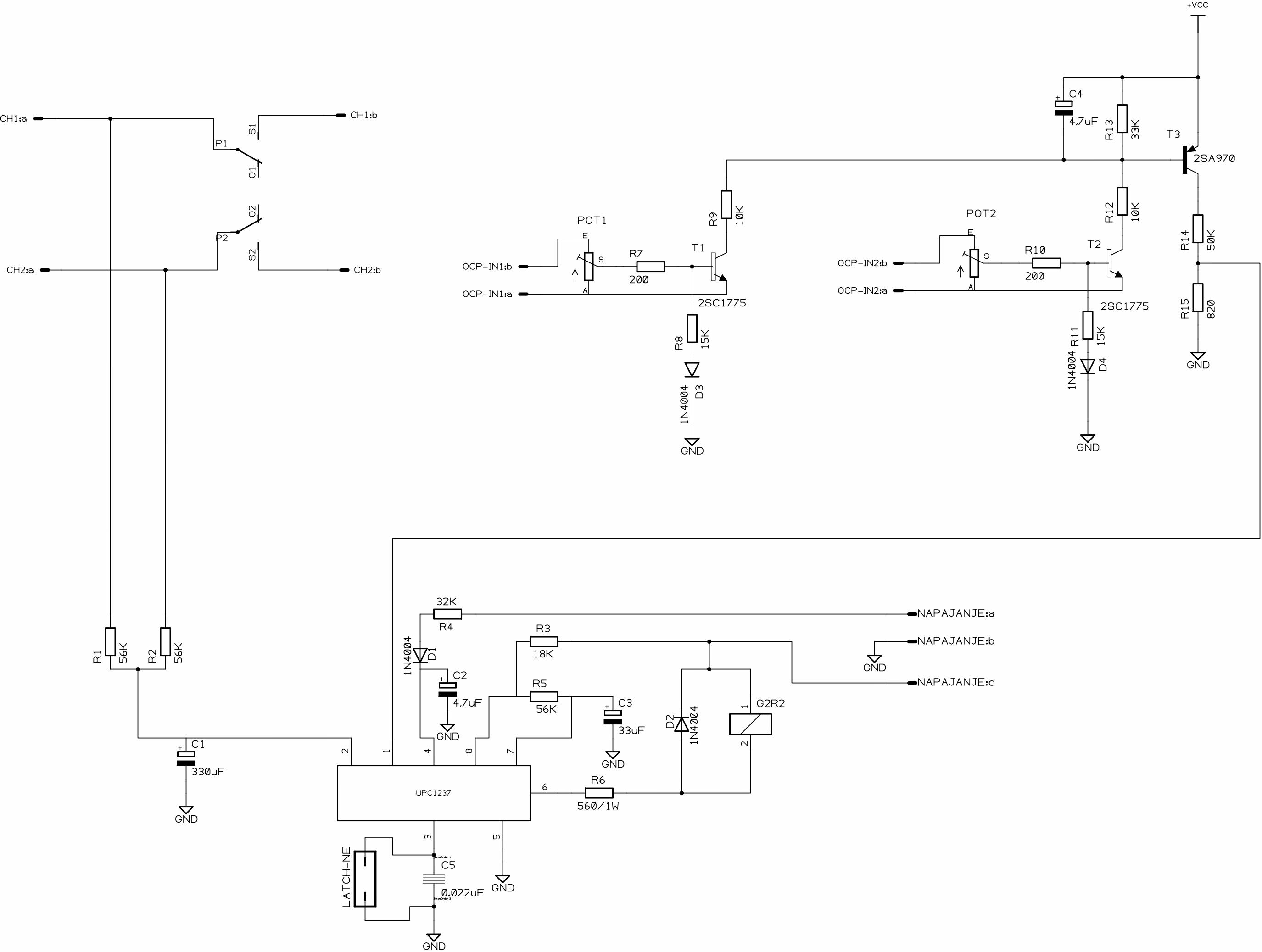
6. Protection board is made around uPC1237, old IC dated from year 1986. which still works excelent and it is enough way of protection for most home made amplifiers.
– Oveload/shortcircuit protection are achived using transistors T1 (for one channel) an T2 (for other), while the purpose of T3 is for conducting current to IC when overload condition happendes. Threshold current(base voltage) can be set with trimer POT1 and POT2.
– DC voltage protection are already built in IC and other components is there for achiving that.
– Latch functions must be used(use capacitor) if using overload/shortcircuit protection because of nature of this kind of protection which is: when shortcircuit protection happendes output current of amp rise, and voltage across source resistor rises and T1/T2 start conducting and colector of T3 gets voltage from +VCC and conducting current to pin 1 of IC; relay brokes off. When releay brokes off it disconnects speaker/short circut/wire and amp current drops, so, voltage on source resistor drops and T1/T2 stops conducting and relay connects again, and now, current rise, voltage rise, transistors conducts … etc etc. SO, protection circuit starts to act as oscilator and does ON/OFF/ON/OFF… of speaker connection, and because of that latch/memory function must be used, so when shortcircuit condition happends it will broke off relay and stays in that condition untill power supply is removed and connected again. And of course, another way of overcurrent protections is fuses in positive and negative rail in power supply which works great. Mosfets can stand current of 12Amps if channel temperatur is keepd beellow 150 deegrees celsius. Here is datasheet of uPC1237: UPC1237. If using only DC protection, no need for latching. And as higher as voltage is, relay will broke faster.
There is also similar ics like ha12002, nte1635, ta7317.
Schematics, PCBs and source code are given here:
Controller board
Atmega8 src code
All sch/pcb are made using Pulsonix 8.0; software that you can buy for ~5000USD.
———————————–
*** Dedicated to Marina ***
———————————–

Hi
Can You give me hex or right code for MCU PGA2311.Regards Robert
LikeLike
you mean code for mcu regarding ic pga2311?
LikeLike
Yes I try make compilation but still no file.I compilation i Eclipse.Sorry for my English.
#include “MAX7219.h”
^
compilation terminated.
make: *** [MAX7219.o] error 1
LikeLike
o, yes, it could be that you nees max7219.h file. did you downloaded?
LikeLike
from where?Inside your file I didnt see.Could You upgrade file?Regards Robert
LikeLike
yes, I can upgrade, but cant don it right know. i can do it later
LikeLike
ok super I have all in PCB but I waiting for code.After Download please give me email.
LikeLike
ok, no problem. i am not sure how find out email at the moment, but i will let you know
LikeLike
ok Thank You.
LikeLike
lcdgsm1@o2.pl send me now if You can for my email.I try preamp.
LikeLike
I sent you an email
LikeLike